高密封截止阀
商品详情
性能特点
技术参数


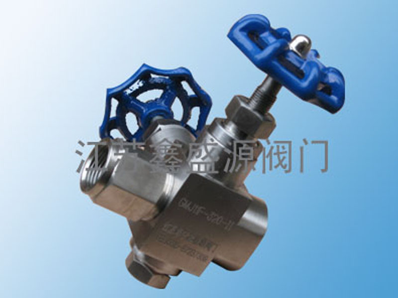
GMJ11高密封截止阀主要用于石油、化工、电力、冶金、制药、轻工等行业的管路上,作启闭装置。 GMJ11(13)F/H型,阀门密封副采用软硬密封材料,实现双重密封,关闭时可达到无泄漏。是电站、炼油、化工装置和仪表测量管路中的一种连接方式的阀门。
产品名称:高密封截止阀
产品型号:GMJ11 GMJ41
工作压力:3000PSI~6000PSI(413bar),高可达10000PSI(689bar)
工作温度:
PTFE填料:-38oC 至 180oC (-100oF 至 356oF)
PPL 填料:-38oC 至 280oC (-100oF 至 536oF)
石墨填料:-24oC 至 480oC (-75oF 至 896oF)
连接端口:螺纹 法兰
适用介质:水 油 气
鑫盛源高密封截止阀优点:
1、两截阀杆设计,上阀杆螺纹淡化工艺处理
2、下阀杆表经经滚压硬化处理上阀杆螺纹的润滑脂与系统介质隔离
3、无旋转的下阀杆垂直运动代替旋转升降,减少阀杆行程对填料的磨擦,手感更轻便
4、阀门在全开位置具有背密封功能
5、可安装手柄或者手轮操作,稳固耐用多种颜色手柄可供选择
6、每只阀门在出厂前均按设计压力的1.1倍进行氮气密封测试,并按额定工作压力的1.5倍水压进行壳体强度测试。
高密封截止阀
高密封截止阀是一种通过创新密封结构实现流体截断的工业阀门,其核心原理在于采用多重密封技术和特殊结构设计来确保在高压、高温等严苛工况下的零泄漏性能。以下是其工作原理及技术特点的详细分析:
1. 基本工作原理
高密封截止阀通过阀杆的轴向运动驱动阀瓣与阀座紧密贴合或分离,实现介质的切断或流通:
强制密封机制:关闭时,阀杆对阀瓣施加机械压力,使阀瓣密封面(通常为平面或锥面)与阀座密封面强制贴合,形成金属硬密封或复合密封。介质压力越高,密封面压紧力越大,形成“压力自紧式密封”。
流向设计:传统设计介质从阀瓣下方进入(低进高出),但现代高密封阀门多采用“高进低出”流向,利用介质压力辅助密封,减少阀杆受力并降低操作扭矩。
2. 核心密封技术
高密封性能通过以下创新结构实现:
波纹管密封:采用双层不锈钢波纹管(如316L)隔离阀杆与介质,彻底消除填料泄漏风险,寿命较传统结构提升3倍以上。波纹管可承受425°C高温和CLASS 800压力等级。
双压力自密封系统:结合阀盖楔形密封环和填料压环,当介质压力超过5MPa时,推动密封环径向膨胀实现自锁,形成“压力越大密封越紧”的效果。
硬质合金密封面:阀瓣与阀座密封面堆焊司太立(Stellite)钴基合金,耐磨、耐冲刷,寿命超10万次启闭循环。
3. 结构特点与性能优势
低摩擦设计:阀瓣与阀座无相对滑动,减少密封面磨损;升降旋转杆式结构降低操作扭矩(仅为同规格闸阀的30%)。
耐极端工况:锻钢阀体与氮化处理的阀杆可承受-196°C至550°C温度范围及200MPa超高压(如OKV系列超高压截止阀)。
在线维护:倒密封结构允许不停机更换填料,部分型号配备可拆卸阀座,便于维修。
4. 典型应用场景
石化与能源:乙烯裂解装置高温切断(425°C)、核电站主蒸汽管道(CLASS 800压力等级)。
超高压系统:石油开采、化工流程中用于40MPa~200MPa的介质控制(如江苏中力OKV系列)。
腐蚀性介质:衬氟截止阀适用于强酸(王水、氢氟酸)和强碱管路,密封圈采用PTFE或石墨材料。
5. 与传统截止阀的对比
特性高密封截止阀普通截止阀密封形式波纹管+硬质合金+自紧结构单一填料或金属密封泄漏等级BS EN 12266-1 A级(接近零泄漏)常规标准泄漏量耐压能力200MPa(超高压型号)通常≤16MPa维护周期10万次启闭以上需频繁更换填料
总结
高密封截止阀通过波纹管隔离、压力自紧密封和硬质合金堆焊等技术的综合应用,解决了传统阀门易泄漏、寿命短的问题。其设计兼顾高强度与低操作扭矩,尤其适合高温高压、腐蚀性或危险介质的精密控制。用户选型时需根据介质特性、压力等级及维护需求选择适配型号(如波纹管密封型或超高压锻钢型)。
Working Principle of High-Sealing Globe Valve
The high-sealing globe valve is an industrial valve designed with advanced sealing structures to achieve reliable fluid shutoff. Its core principle lies in multi-layer sealing technologies specialized structural designs to ensure zero leakage under extreme conditions such as high pressure temperature. Below is a detailed analysis of its working mechanism technical features:
1. Basic Working Principle
The high-sealing globe valve controls fluid flow through the axial movement of the stem, driving the disc to tightly engage disengage the seat:
Forced Sealing Mechanism: When closed, the stem applies mechanical pressure to press the disc sealing surface (typically flat conical) against the seat, forming a metal-to-metal composite seal. Higher fluid pressure increases the sealing force, creating a "pressure-assisted self-tightening seal."
Flow Direction Design: Traditional designs feature fluid entering below the disc (low-inlet, high-outlet), but modern high-sealing valves often adopt a "high-inlet, low-outlet" flow path, utilizing fluid pressure to enhance sealing while reducing stem load operating torque.
2. Core Sealing Technologies
High-sealing performance is achieved through the following innovations:
Bellows Seal: Dual-layer stainless steel bellows (e.g., 316L) isolate the stem the medium, eliminating packing leakage risks entirely. Bellows withstand temperatures up to 425°C pressure ratings of CLASS 800, with a lifespan 3x longer than conventional designs.
Dual Pressure Self-Sealing System: Combines a wedge-shaped gland ring packing compression ring. When pressure exceeds 5MPa, the sealing ring expands radially to self-lock, creating a "higher pressure, tighter seal" effect.
Hard-Alloy Sealing Surfaces: Disc seat surfaces are welded with Stellite cobalt-based alloy for wear erosion resistance, supporting over 100,000 open-close cycles.
3. Structural Features & Performance Advantages
Low-Friction Design: The disc seat have no relative sliding motion, minimizing wear. A rising-rotating stem mechanism reduces operating torque (only 30% of gate valves with equivalent specifications).
Extreme Condition Resistance: Forged steel bodies nitrided stems endure temperatures -196°C to 550°C ultra-high pressures up to 200MPa (e.g., OKV series ultra-high-pressure globe valves).
Online Maintenance: Backseat designs allow packing replacement without shutdown. Some models feature removable seats for easy repairs.
4. Typical Applications
Petrochemical & Energy: High-temperature isolation in ethylene cracking units (425°C), nuclear power plant main steam pipelines (CLASS 800).
Ultra-High-Pressure Systems: Oil extraction chemical processes requiring 40MPa–200MPa control (e.g., Jiangsu Zhongli OKV series).
Corrosive Media: Lined PTFE globe valves for strong acids (aqua regia, hydrofluoric acid) alkalis, using PTFE graphite seals.
5. Comparison with Conventional Globe Valves
FeatureHigh-Sealing Globe ValveStandard Globe ValveSealing TypeBellows + hard alloy + self-tighteningSingle packing metal sealLeakage ClassBS EN 12266-1 Grade A (near-zero leakage)Standard leakage ratesPressure CapacityUp to 200MPa (ultra-high-pressure models)Typically ≤16MPaMaintenance Cycle100,000+ cyclesFrequent packing replacements
Summary
High-sealing globe valves integrate bellows isolation, pressure-assisted sealing, hard-alloy surfacing to overcome traditional valve limitations like leakage short lifespans. Their design balances high strength with low operating torque, making them ideal for precise control of high-temperature, high-pressure, hazardous media. Selection should consider fluid properties, pressure ratings, maintenance needs (e.g., bellows-sealed ultra-high-pressure forged steel models).